Cable Encyclopedia
Cinch (RCA)
Cinch (RCA) is a widespread, strictly speaking incorrect term for non-standardized plug-in connectors for transmitting electrical signals mainly to coaxial cables. No screen is necessary in seldom cases, power supply, loud speaker connection or the connection of consumer devices (stereo, television, etc.) A single line pair is frequently used.
Cinch /RCA plug (Image 1), Cinch / RCA socket (Image 2):
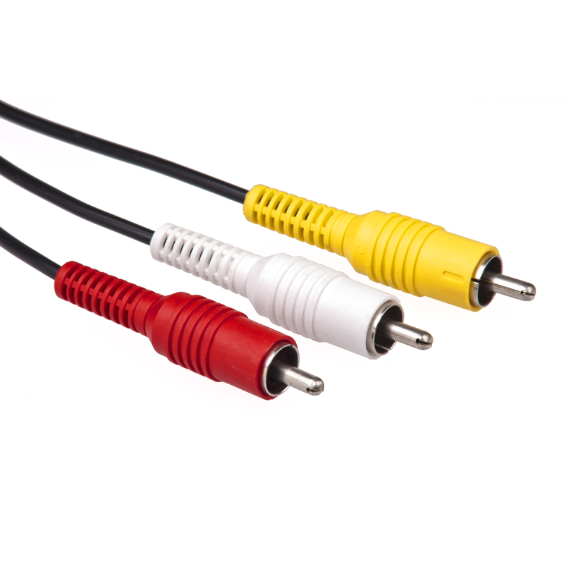
Image 1: RCA Male
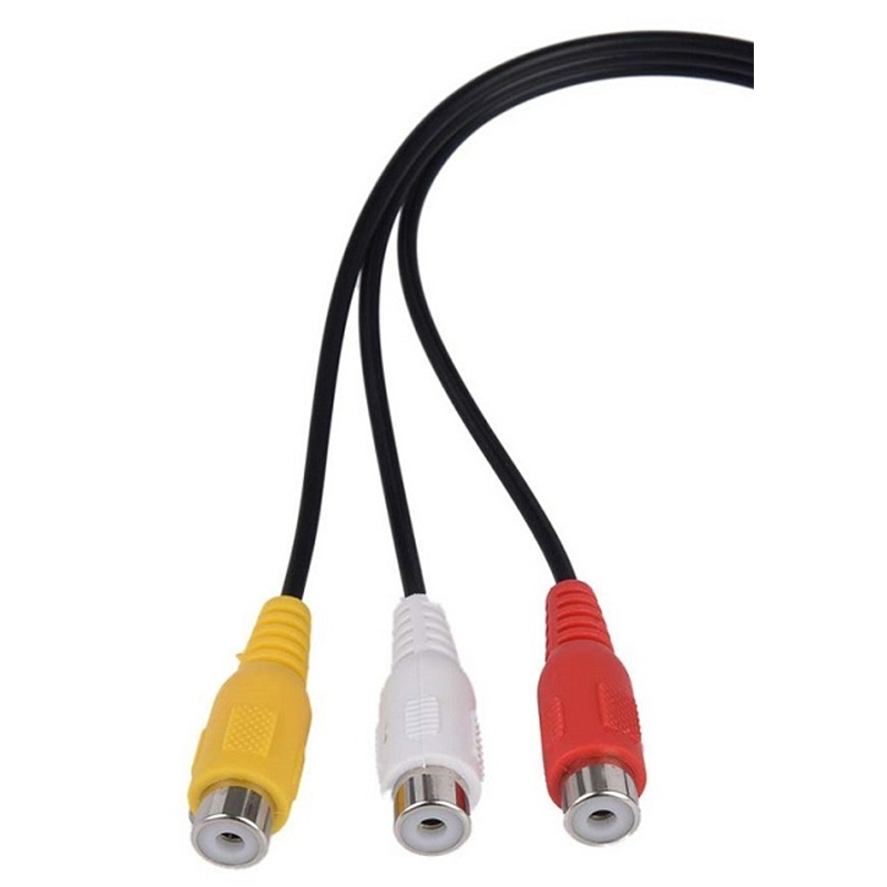
Image 2: RCA Female
These plug-in connectors are used especially in the home audio and video area (audio visual media), where uniform colour coding is used:
Colour coding in the video area:
YUV = YELLOW: Composite Video (YUV)
RGB = RED: Pr (Component Video, colour difference)
GREEN: Y (Component Video, brightness)
BLUE: Pb (Component Video, colour difference)
Colour coding in the audio area:
Standard
WHITE: Left analog channel (occasionally also BLACK or GREY)
RED: Right analog channel
Special Forms
ORANGE: Digital-Audio (S/P-DIF)
BLACK: Subwoofer or center channel
GREY: Loudspeaker (seldom)
Cable which has four equal connections is sometimes used for connecting audio devices which can also record to cover both inputs & outputs of the device in stereo:
WHITE: Left channel for playback
RED: Right channel for playback
BLACK: Left channel for record
YELLOW: Right channel for record
Displayport
The DisplayPort plugs are considerable smaller that D-Sub and DVI plugs and there-fore allow easy integration of more than two plug-in connections to graphic cards so that they are better for portable display devices, such as notebooks, for example.
Optional locking is also planned, unlike the competing HDMI plug (see the following image):
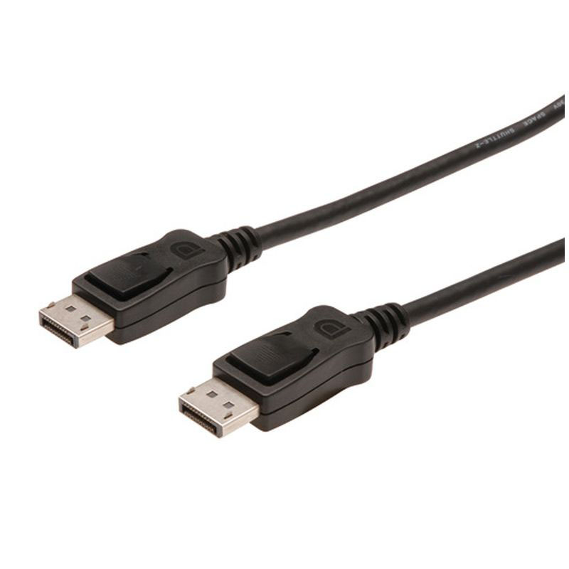
Displayport Locking Connectors
Our standard Displayport version 1.2a has a data rate of 17.28 Gbit/s in High Bit Rate 2 (HBR2) mode, which allows increased resolutions, higher refresh rates, and greater colour depth, such as 3840 × 2160 at 60Hz 10bpc RGB. Other improvements include multiple independent video streams (daisy-chain connection with multiple monitors) called Multi-Stream Transport (MST), facilities for stereoscopic 3D, increased AUX channel bandwidth (from 1 Mbit/s to 720 Mbit/s), more colour spaces including xvYCC, scRGB, and Adobe RGB 1998, and Global Time Code (GTC) for sub 1 μs audio/video synchronisation. Also Apple Inc.’s Mini DisplayPort connector, which is much smaller and designed for laptop computers and other small devices, is compatible with the new standard. 1.2a may optionally include VESA’s Adaptive Sync.
Our DisplayPort version 1.3 increases overall transmission bandwidth to 32.4 Gbit/s with the new HBR3 mode featuring 8.1 Gbit/s per lane (up from 5.4 Gbit/s with HBR2 in version 1.2), for a total data throughput of 25.92 Gbit/s after factoring in 8b/10b encoding overhead. This bandwidth is enough for a 4K UHD display (3840 × 2160) at 120Hz with 24 bit/px RGB colour, a 5K display (5120 × 2880) at 60Hz with 30 bit/px RGB colour, or an 8K UHD display (7680 × 4320) at 30Hz with 24 bit/px RGB colour. Using Multi-Stream Transport (MST), a DisplayPort port can drive two 4K UHD (3840 × 2160) displays at 60Hz, or up to four WQXGA (2560 × 1600) displays at 60Hz with 24 bit/px RGB colour. The new standard includes mandatory Dual-mode for DVI and HDMI adapters, implementing the HDMI 2.0 standard and HDCP 2.2 content protection. The VESA’s Adaptive Sync feature in DisplayPort version 1.3 remains an optional part of the specification
Digital Visual Interface (DVI)
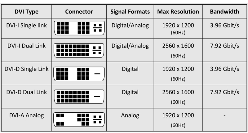
These can transmit analog (DVI-A, seldom used), analog and digital (DVI-I), or only digital (DVI-D) signals, depending on the pin configuration of a DVI connection. Two digital signals can also be transmitted at the same time (Dual-Link, 24+1 PIN / 24+5 PIN), so that higher resolutions (QXGA, max 2560 x 1600 pixels, for example) are possible. There is a maximum of 1915 • 1436 pixels with 4:3 resolutions for a single link cable and a picture refreshment rate of 60 Hz. The maximum resolution for single link cables is therefore 1600 • 1200 pixels (UXGA) for this reason.
There are usually quality advantages from digital data transmission compared to an analog connection with a VGA- or SCART cable. Precisely two signal conversions are necessary for the latter mentioned cable types (not necessary for digital monitors): from digital to analog at the video output and back from analog to digital in the monitor.
A VGA screen can be operated by using a purely passive adapter can be operated at a socket where there is a combined signal (DVI-I, 18+5 PIN / 24+5 PIN).
The maximum length of line for connection to a DVI terminal unit (monitor) depends on the quality of the connection line and also on the quality of the terminal unit howe-ver. A maximum line length of 5–10 meters usually has to be observed. A DVI amplifier has to be used if there is a greater distance. The picture will be more out of focus otherwise for analog transmission: the connection will fail completely at some time or other for digital transmission.
The audio signal is not transmitted with a connection consisting of HDMI to DVI. A separate connection (via Cinch/RCA, for example) is necessary here.
Here is an overview of the most frequently used DVI cables:
HDMI
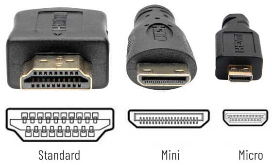
HDMI Connections
HDMI 2.0 increases the maximum bandwidth to 18.0 Gbit/s. HDMI 2.0 uses TMDS encoding for video transmission like previous versions, giving it a maximum video bandwidth of 14.4 Gbit/s. This enables HDMI 2.0 to carry 4K video at 60Hz with 24 bit/px colour depth. Other features of HDMI 2.0 include support for the Rec. 2020 colour space, up to 32 audio channels, up to 1536 kHz audio sample frequency, dual video streams to multiple users on the same screen, up to four audio streams, 4:2:0 chroma subsampling, 25 fps 3D formats, support for the 21:9 aspect ratio, dynamic synchronization of video and audio streams, the HE-AAC and DRA audio standards, improved 3D capability, and additional CEC functions
Audio Jack Connectors
Our 3.5mm shaft diameter cables (usually for portable devices (MP3 players, sound cards and small head phones) are also known as a micro plug.
The 6.35mm diameter connection is for stereo systems and practically all devices from music production, such as mixing desks, effect devices, synthesizers, keyboards, E pianos, E guitars and guitar amplifiers. They tolerate sufficient mechanical load and have a large contact surface.
Various adapters are available on the market to connect devices with the varying connection sockets by using a single cable. These are usually pushed on or screwed on. One should always try to avoid using adapters wherever necessary. However, since the number of contacts which are often faulty anyhow is increased by the adapter so that data transmission becomes worse.
The jack plug types with two (Mono), three (Stereo) and four (Stereo + extra) contacts. The stereo plug with the extra function is a variation of the stereo plug. Some multi channel contacts for PC and cameras use these types of 4 pole connections because of space problems.
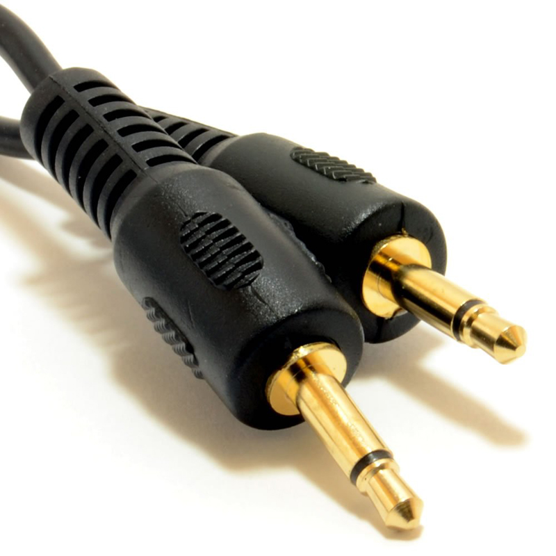
Mono-Plug (2-pole)
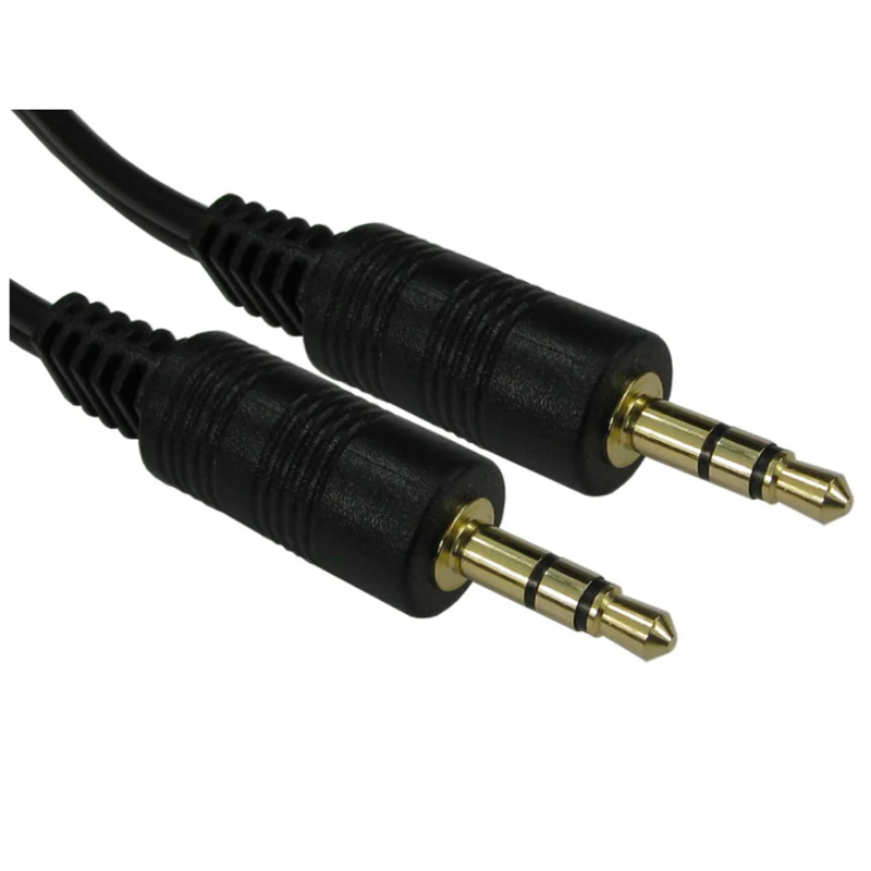
Stereo-Plug (3-pole)
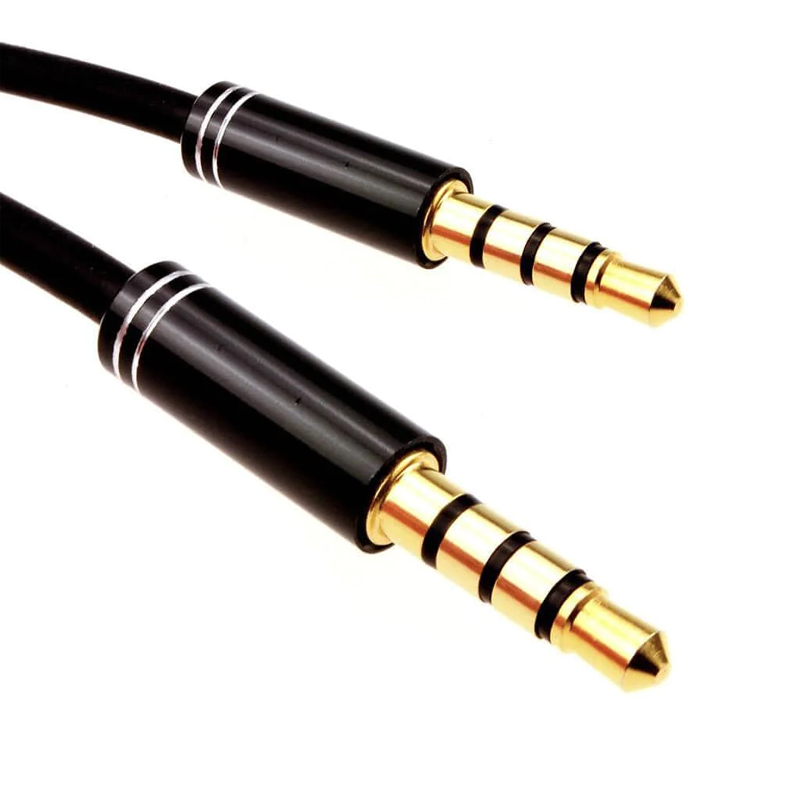
Stereo with extra function (4-pole)
Copper Patch Cables
Four paired cables area used as a matter of preference in current network installation. The ISO/IEC-11801 (2002)E, a new description scheme in the form of XX/YZZ has been introduced, since the old descriptions were not uniform and often lead to confusion or were even contradictory.
We therefore have the following:
· XX for complete screening: U = unscreened, F = foil screened, S = braided screen, SF = braid and foil screen
· Y stands for paired strand screening: U = unscreened, F = foil screened, S = braided screening
· ZZ always stands for TP = twisted pair
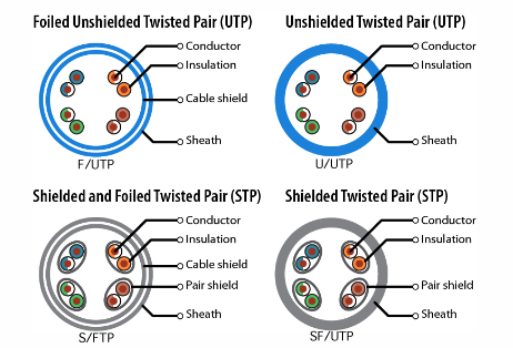
Categories complying with one respective requirement profile have been introduced for easier classification of the individual cables. Categories 1 and 2 are only informally defined; categories 3 and 4 are no longer commercially relevant. Here are the most important categories for network installation:
CATEGORY 5: Cat 5 cables are the mainly relevant installed basis for working frequencies up to 100MHz. Cables of category 5 are often used in structured cabling of computer networks, such as Fast or Gigabit Ethernet for example.
CATEGORY 6: Cat 6 cable is defined by EN50288. Cat 6 cables are used for working frequencies up to 250MHz. The rate of transmission deteriorates in longer lengths, smaller overlaps do not present any problems, depending on extraneous factors. Fields of application for Cat 6 are speech and data transmission and also multimedia.
CATEGORY 7: Cat 6 cables are used for working frequencies up to 600 MHz. A Cat 7 cable satisfies the IEEE 802.3an standard as is therefore suitable for 10 Gigabit Ethernet.
Power Cables
A harmonized system of abbreviations has been developed within Europe by CENELEC (European Committee for Electrotechnical Standardization) for the uniform identification of electrical lines (see table the table on the next page). The type abbreviations for the lines state the construction type and the intended use for the electrical lines in the electrical installation. The identification contains all the necessary information for the construction and optional uses of the line (materials and permitted voltages, for example). National identifications are normal for some line types however.
Different connectors specified in the IEC standard (International Electrotechnical Commission) IEC 60320 are used, depending on the device to be connected.
The following images show the most frequent connectors:
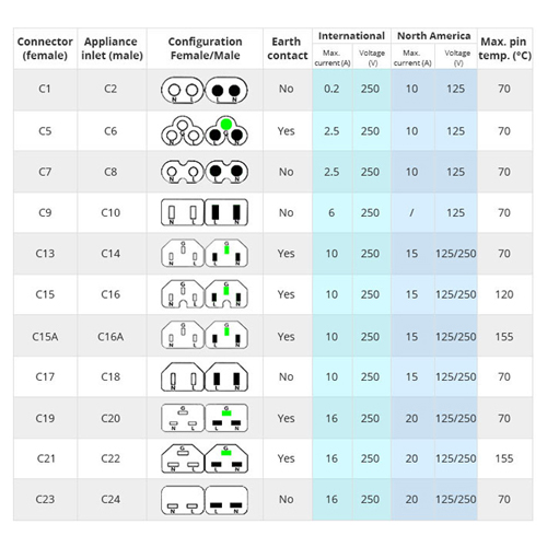
IEC Connectors & Sockets
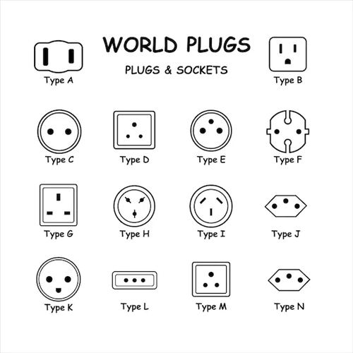
World Plugs
USB Cables
Four strands are required in a USB cable. Two strands transmit the data, the other two supply the connected device with a voltage of 5V. The cables must be screened differently according to speed.
Five additional contacts are necessary in the plugs for the USB 3.0 version in order to guarantee high data rates.
USB allows transmission of data to a device with 1.5 Mbit/s, 12 Mbit/s or with 480 Mbit/s. The transmission speed in Version 3.0 rises to 5 Gbit/s where USB 3.0 is downwards compatible to the existing USB versions (1.1 & 2.0).
Transmission speed USB Versions:
High-Speed (480 Mbit/s) 2.0
Super-Speed (5 Gbit/s) 3.0
Super-Speed (5 Gbit/s) 3.1 Gen 1
Super-Speed (10 Gbit/s) 3.1 Gen 2
We also can supply USB 3.2 with speeds of 20 Gbit/s, and now USB 4.0 at up to 40 Gbit/s.
The lengths of USB cables from the hub to the device are limited to five or three meters. depending on the specifications.
The plugs of a USB cable are designed so that the poles cannot be accidently changed or confused (except for the USB Type C connector, which is reversible). Flat plugs (type A) and a practically square plug (type B) are used in the direction of the PC/host controller, hub (upstream) and towards the connected end device (Downstream) or the cable is already installed in the end device.
There is a more compact type of plug for end devices with very little space (digital cameras, cell telephones, external 2.5“ hard disks, for example) which are designated as Mini and Micro USB plugs. There are differing construction types here depending on the device manufacturer with many varying connection pins.

VGA Cables
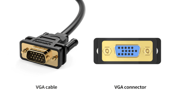
The output of the graphic card is always a socket (hidden contact pins). The input at the display device can have both genders, depending on the type. This is usually a socket as well (all modern tube and LCD monitors), so that a connection cable is required between two plugs (exposed contact pins).
VGA cables are clearly prone to faults, depending on quality and already with lengths below 5m. A suitable high frequency cable with a coaxial structure is therefore advantageous for the colour channels. VGA is generally only suitable to a limited extent for high resolutions above SXGA (1280×1024 pixels), since fuzziness can appear with analogue tube displays and because digitalisation is very demanding in the display controller of the flat screen monitor when LCD monitors are in use.
The DVI interface which can also be used to transmit an analogue VGA signal is the digital successor to the VGA interface. An adapter can therefore be used to operate VGA devices at DVI outputs, providing the appropriate signal lines area also supplied with an analogue signal (only the case with DVI-I and DVI-A).
Fairline also offer VAT included prices at Computerstar. Find your technology solution online and order with ease!

